The Land
Cruiser Restoration Project
Page 1 2 3 4 5 6 7 8 9 10 11 12 13 14 15 16 17 18 19 20 21 22 23 24 25 26 27 28 29 30 31 32 33
On this page I am trying out a little different format. When I sized these photos after I scanned them in, I kept the file size well under 100kB, and changed the way the jpgs are saved to a "progressive" scan, which means the image appears after only about a third of the image has downloaded. It takes a total of three passes before the full image is clear, but this way I don't have to deal with making thumbnails, which are normally about the same file size a one third of the full size image anyway. Please feel free to email me any comments on this format. I'm still on a slow dial up connection, but more and more people have broadband, so hopefully it won't be as much of an issue as it was when I started this site back in 1998.
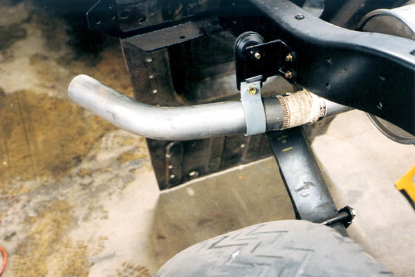
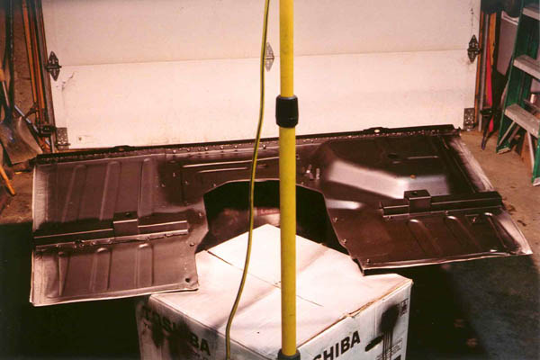
As mentioned in the last page, they don't make the exhaust pipe clamps any more, so for the tailpipe, I fabricated one like the original factory ones. Below is a photo showing it installed with all the rest of the new factory hardware. The piece behind the rig is the floor pan leaning up against the rear frame crossmember.
Below is a view of the clamp and hanger on the other side of the muffler. I used all factory hardware when I assembled the exhaust system. While I used a lot of aftermarket JIS metric fasteners on a lot of things on this project, the CAD plated factory fasteners should last longer in the demanding application of the exhaust system.
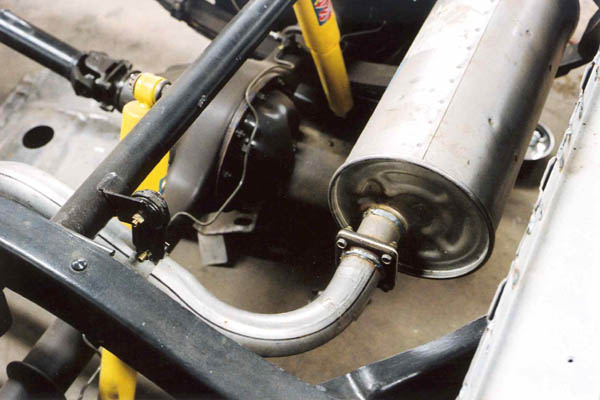
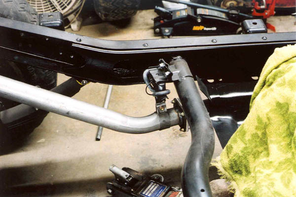
The strange looking exhaust pipe support below is the complete factory arrangement. The two rubber donuts are supposed to provide support, yet allow the engine to be somewhat isolated on it's own rubber mounts, which distribute the stress of the engine moving separately from the frame along the full length of the exhaust.
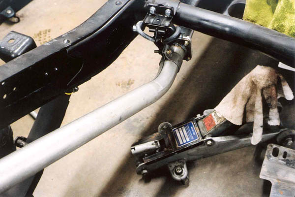
A view from the side shows it a little better. There are wire bails to keep it from falling completely off if the rubber donuts fail. Like all rubber parts, they eventually wear out.
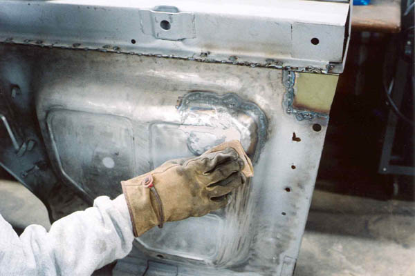
As I mentioned on a previous page, the holes under the repaired corner of the floor pan where the fuel tank sits are filled in with body filler. In the photo below, I am sanding the filler down flush with the remaining metal.
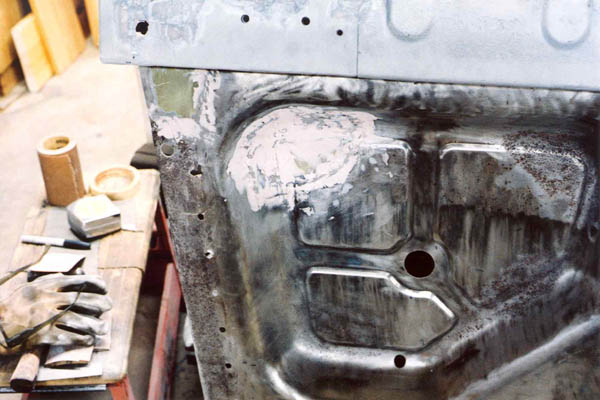
After I'm done with the bottom I then do the top (interior) side of this repaired section. Even though I ground down the welds, it was still fairly lumpy and it took a couple of layers to get it smooth.
After all this prep work is done, it's finally time to paint. I put several coats of zero rust on the bottom. I masked the edges on each side where it will be welded to the rocker panels. Those get sprayed with the zinc weld through primer.
The repaired section under the driver's side feet is getting more zinc paint. There will still be a fair amount of welding going on in this area when it is assembled with the rocker panels and mated to the floor pan. I sanded and sand blasted a great deal up under the dash and on the inside of the firewall, but large sections were still in pristine condition so on those I just scuff sanded for repainting.
Next I painted the inside of the firewall and up under the dash area with zero rust. On the right you can see where it is painted with the zinc weld through in anticipation of welding it to the floor pan.
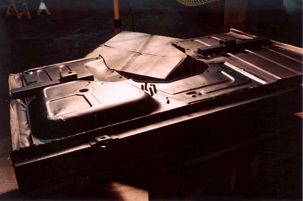
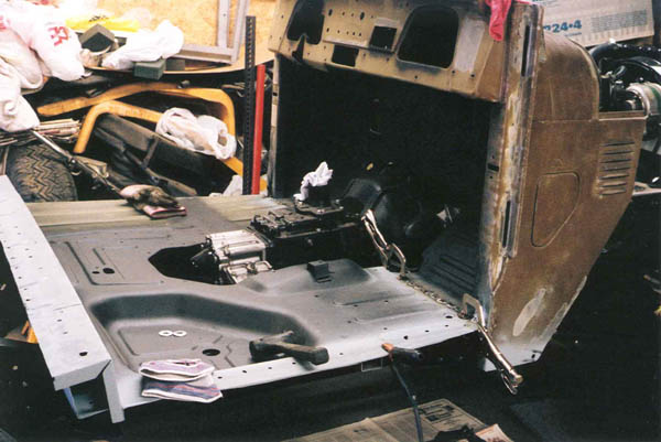
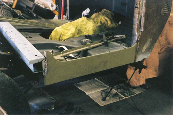
This work was being done in April, 2005 shortly before Cruise Moab. As many of you know, work on this project generally comes to a screeching halt in order to focus wrench time on getting my trail rig ready for Moab. But I was on such a roll, I didn't want to stop! My friends Scott Yoder and Joe Rounsavel came over for a jam one Sunday afternoon for a mini reunion of Hydraulic. We had a blast, and even though we were all rusty we had a great time playing. I enlisted their help to lift the cowl and floor pan onto the body mounts while I put some bolts through to keep it aligned. Then they held it in place while I made some tack welds to start joining these parts together.
After they left, I came back and added more tacks until the weld was complete on the top side. After the tub is assembled I will remove it (with more help from my friends of course!) and get the undersides. But this is quite a milestone in this project and I am excited!
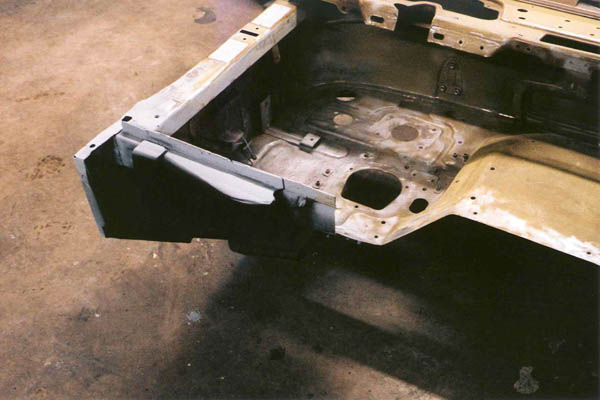
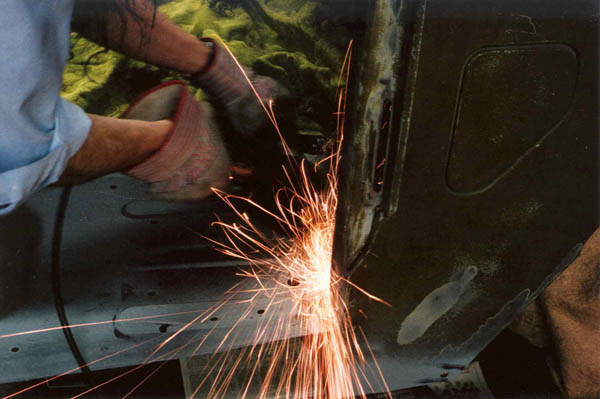
Even though my welding is getting better, there is always plenty of grinding to do afterward. Here I am grinding the welds on the junction between the floorpan and the A-pillar to make a flush surface for the rocker panel front edge.
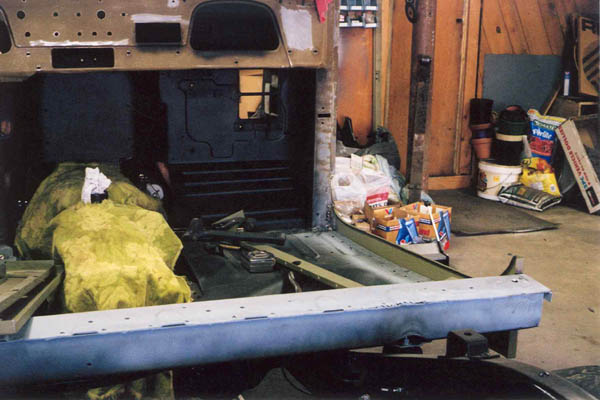
I dug out the rocker panels from my pile of parts from CCOT and went about trying to figure out which way they go in. It helps to have another FJ40 around to eyeball. Even though there are some differences between the 1971 and the 1976, they are similar enough to get a good idea how things are supposed to go together. After I got that figured out I started to test fit them. The passenger side was a tight fit.
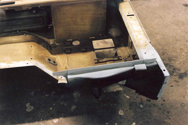
I welded up the right side outer rocker, then ground down the excess welds. I'm a little concerned that the end of the box section isn't quite square and perpendicular with the edge of the rear of the rocker, not sure if this may cause me problems later on. I had clamped it as well as I could before welding, but that's the best I could do with the big vice grip c-clamps.
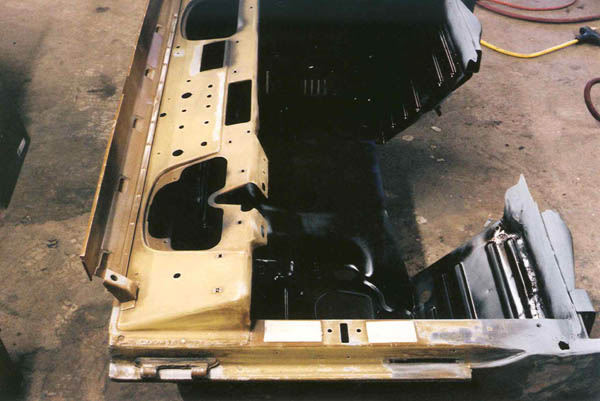
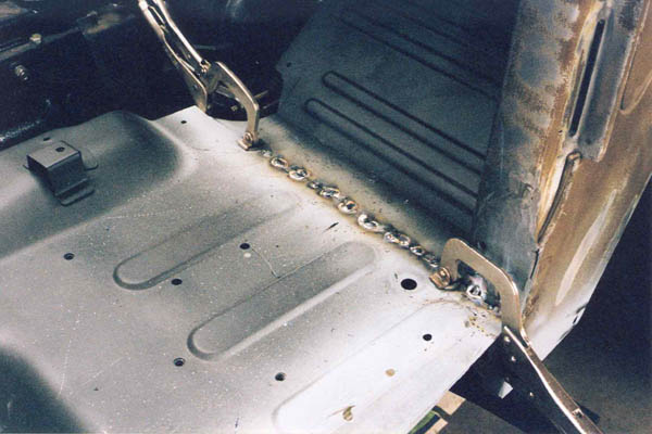
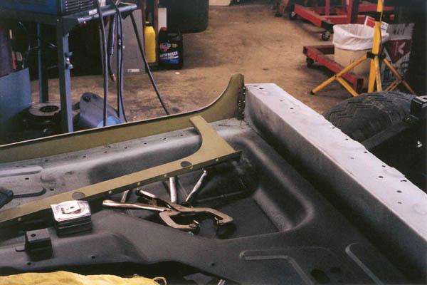
A view from the rear reveals the welds on the inside at the A-pillar. At this point, I haven't welded the floor pan to the rocker yet. As a result of the way I had cut the old rockers from the floor pan, there is a 1/8 inch gap running all along the edge of the floor pan between the pan and the inside surface of the rocker panel. I would later solve this by adding a 1/4 x 1/4 x 1/8 angle iron along each edge of the floor pan between the pan and the rocker.
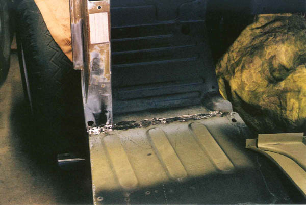
Below, you can see the welds to the front of the box section. You can also see how the edge of the floor pan sags a little where it is unsupported. As mentioned, I ended up fixing this with some small angle iron when I welded it to the rocker panel.
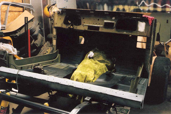
The driver's side floor pan welds to the cowl are ground down. Right about here I had to suspend the project to get my trail rig ready for Moab. A host of other projects after Moab, including the tail pipe for my FJ45, seen on the tech tips page, and fabricating a new winch bumper for my 71 kept me from resuming this until late June. But as of this writing over the 4th of July weekend, I have almost a full roll of exposed film in my camera and have welded the driver's side out rocker panel in, and welded the floor pan sides to the rocker panels.
Page 1 2
3 4 5
6 7 8
9 10 11
12 13 14
15 16 17
18 19 20
21 22 23
24 25 26
27 28 29 30
31 32
33
home what's
new cruiser links
trail reports cruiser
sightings land cruiser tribute tech
tips photos maps
band links misc links
profile email