The Land Cruiser Restoration Project
Resto Home Page
Page 1 2
3 4 5
6 7 8
9 10 11
12 13 14
15 16 17 18
19 20 21
22 23 24
25 26 27
28 29 30
31 32 33
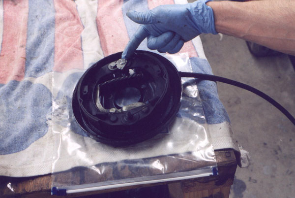
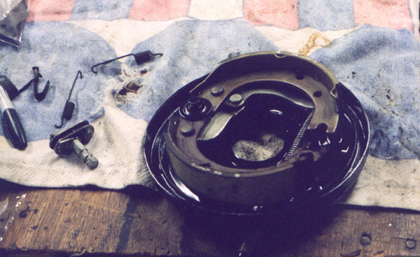
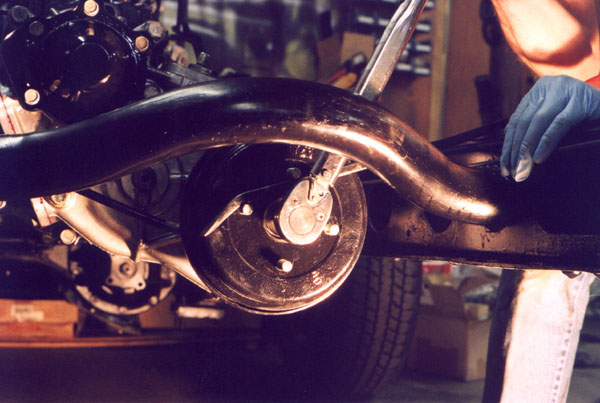
Now that the transfer case was done, the next step was to rebuild the parking brake. It never worked well since I have owned this rig, but it turned out that the shoes were worn very thin. I suspect a PO drove it some distance with the parking brake engaged. I already ordered in new shoes and a new cable so this was going to be straightforward. The cam adjuster, seen below at a medium setting, was already at it's largest setting. New shoes will solve this.
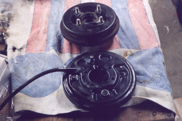
The two photos below show front and back of the parking brake backing plate with shoes and hardware, and the drum itself.

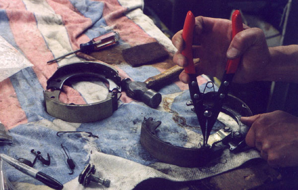
The same c-clip pliers I use on my birfields prove very helpful in removing the horshoe retaining clips from the brake linkage pins. I found these same horshoe clips in my daughter's 1985 4runner rear drum brakes, so I guess they must be a Toyota staple. This type of plier is very handy. In the next photo, the brake backing plate has been wirewheeled, cleaned and painted, and the new shoes installed. Next, the retracting springs are installed.
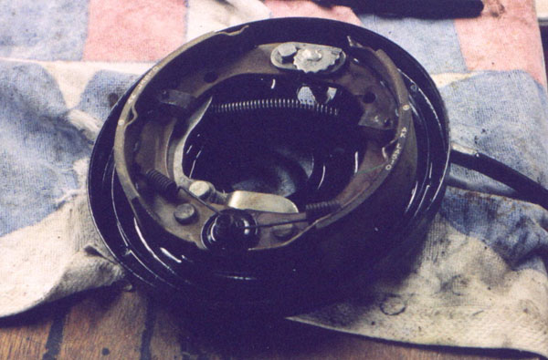
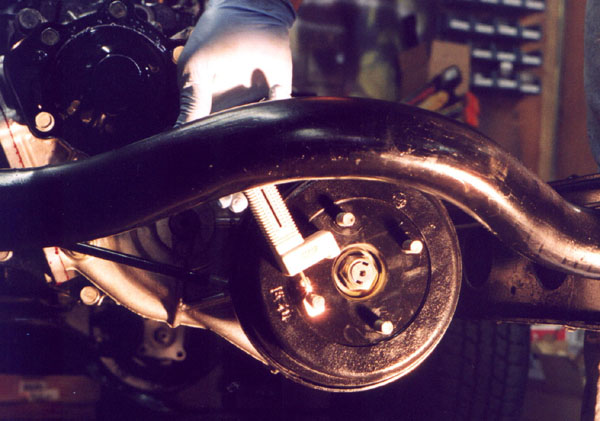
Below, you can see the assembly installed onto the speedo housing on the back of the transfer case. Note at the bottom of the parking brake shoes, there is a spring missing. It is supposed to go across the two shoes horizontally, and helps tension on the bottom, cam side. I got the whole thing installed, then discovered the spring in a ziplock bag on my workbench. Do'oh!!!! I had to drain the t-case 90wt., and remove the drum and then install that silly spring. Glad I caught it now though :-)
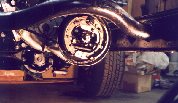
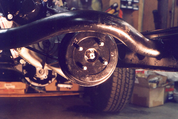
Below, the drum is installed, then the stake nut is torqued down, using a pry bar on the studs to hold the drum, then next a fish scale is used to verify proper preload on the transfer case output shaft bearings and last, the nut is staked to the output shaft.

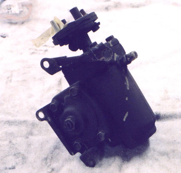
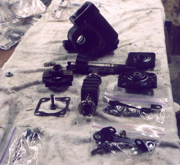
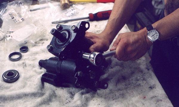
Next up is the steering box. I've never been inside one before, but that's also true of a lot of the sub-systems in this cruiser. Between the factory and Hayne's manuals, and more wrenching experience, this turned out to be straightforward and fun. First I took a shot of what it looked like when I started.
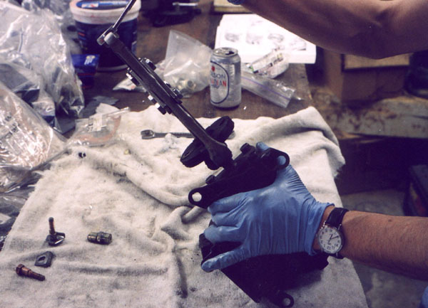
First off, I pulled the rag joint off the worm gear shaft. A two jaw puller works great for this. Yes, thats a Molsen in the background. My GWN friends would take me oot and shoot me for drinking crappy beer, eh, but it was actually there to catch brake fluid. Take off you hoser!
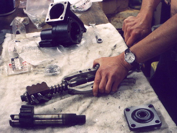
Below, the sterring box is disassembled. The box itself is in the back. The cover plates for the worm gear shaft and sector shaft are on the top and bottom right, respectively. In the middle the sector shaft is laying horizontally and the worm gear shaft, with bearings is vertical below that. Left is rag joint, worm gear shim and adjusting bolt. Right is brackets and bolts.
Once everything was cleaned up in the parts sink, all outer parts were wirewheeled and then painted with an undercoat of Zero Rust, and then a top coat of Ace epoxy enamel. Visual inspection shows that the bearing race closest to the rag joint is pitted, but the one at the bottom is fine. A new bearing and race is ordered in from Mountain States Toyota and the old one is pulled off with that same two jaw puller.
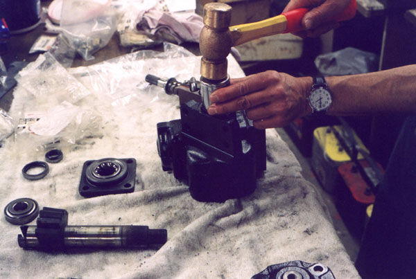
After the new race and bearing came in they were pressed onto the worm shaft. Next is putting a new sector shaft seal into the side of the box.
Pre greasing the bearings, much like packing roller bearings, and then installing the adjdusting screw, with it's plate into the sector shaft.
Next is that all-important shim to set the ball bearing preload on the worm gear shaft.

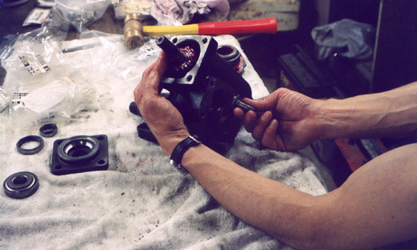
One of the last tasks was tightening down the bolts that are shared between the sector shaft retaining plate and the heat shield that goes between the box and the exhaust manifold. These photos weren't developed yet, so I had to rely on memory and common sense as to how these darn brackets were suppsed to be bolted on. The manuals are no help on the backet orientation.
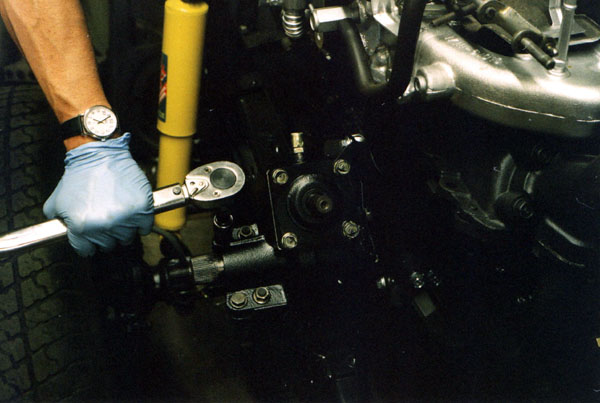
Finally, all is assembled and checked for proper preload, and then torqued down to the pedestal. Cool cruisers of Texas supplied the new rag joint ("coupler assembly") that will be seen in the next page. This summer of 2003 I have been making steady progress on this project, and of this writing have 96 more photos already done of the axle and differential rebuilds.
Page 1 2
3 4 5
6 7 8
9 10 11
12 13 14
15 16 17 18
19 20 21
22 23 24
25 26 27
28 29 30
31 32 33
home what's new cruiser links trail reports cruiser sightings land cruiser tribute tech tips photos maps band links misc links profile email