The Land Cruiser Restoration Project
Resto Home Page
Page 1 2
3 4 5
6 7 8
9 10 11
12 13 14
15 16 17 18
19 20 21
22 23 24
25 26 27
28 29 30
31 32 33
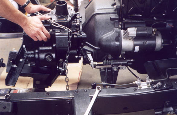
July 2002, and the tranny was finally ready to be bolted back on to the back of the bellhousing. Where I had used a cherry picker to support it when I pulled it, this time I used the tranny adapter that goes on top of a regular floor jack. This adapter had proved utterly useless when I was stabbing the tranny/t-case into the back of the F in my 71, it was more useful in this instance. Without the t-case on the back to make everything off-center, it held the weight of the tranny while I stabbed the input shaft into the (prealigned) clutch friction disk and thence to the pilot bearing in the back of the crankshaft. Once you get it stabbed, thread the bolts in a couple of turns as seen in the photo, then wiggle it in some more before tightening the bolts.
The two photos below show a left and rear views of the installed tranny.
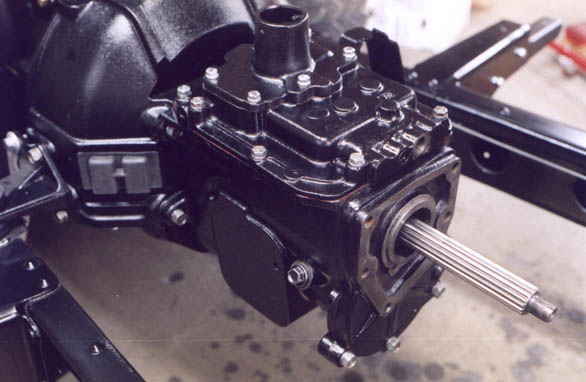
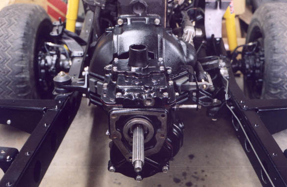
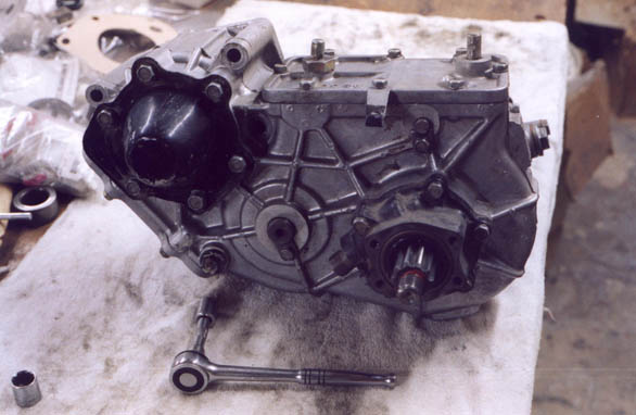
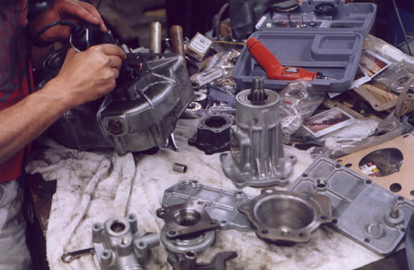
The next big step is going through the transfer case. Even though the idler thrust clearance was within spec, there are a number of things that simply require visual inspection and direct measurement and thus require complete teardown. The photo below is after cleaning up the outside, but before disassembly. The tranny output shaft cover is at upper left, and the rear of the t-case output shaft is at lower right. Note the cast iron speedo gear housing. In the middle, bottom, you can see the end of the idler shaft and it's retainer. Top, right is the end of the shaft and retainer for the shaft that the hi/lo shift fork slides along. Lower left is the oil drain plug. This will be replaced with new.
First I removed the cover from the rear of the tranny output shaft bearings. Notice that the bearings for the tranny output shaft are both (front and rear) ball bearings, while the bearings for the t-case output shaft are tapered. We haven't gotten to the output shaft bearings, but the distinction is important. Whenever you have ball bearings, you just bolt it up tight enough so it woun't fall off or move. But with tapered bearings, like on your front wheel bearings and kingpin (trunion or knuckle), pinion or carrier, the preload is set with shims so the bearings are exactly tight. Not more, not less. We'll get into this a little more when it's time to put it back together.
Off comes the breather. It's a one way check valve intended to let air out when it gets hot inside the t-case, but not let water or dust in. Often, the trick is to replace this with a hose up to a high, dry and clean spot.
Next the top cover comes off. This holds the pivot for the shift fork for switching between low range and high range. The fork itself just sets in there, and slides front to back on the shaft.
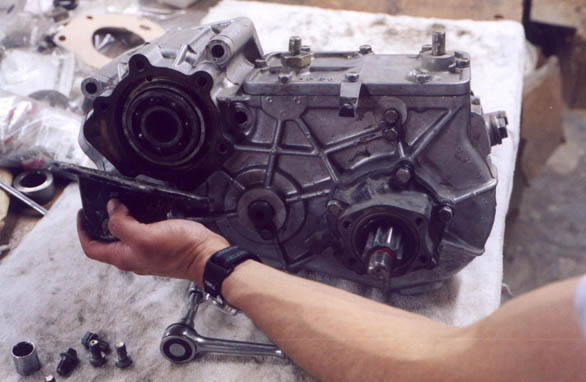
Then the e-brake mounting/speedo gear housing comes off the back of the output shaft. Remember what I said about bearing preload? Not pictured here, but very important, is the shim that goes between the shiny surface you see on the housing in my hands, and the outer bearing race for the rear output shaft. This shim determines the preload on the entire output gear cluster.
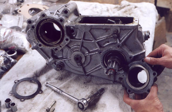
In my hand are the ball, spring and retaining nut for the 4WD shift shaft. As you might imagine, it's pretty important to get all this stuff back together in the right order. I took these photos as much for me as for you!
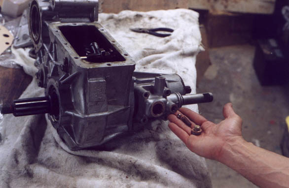
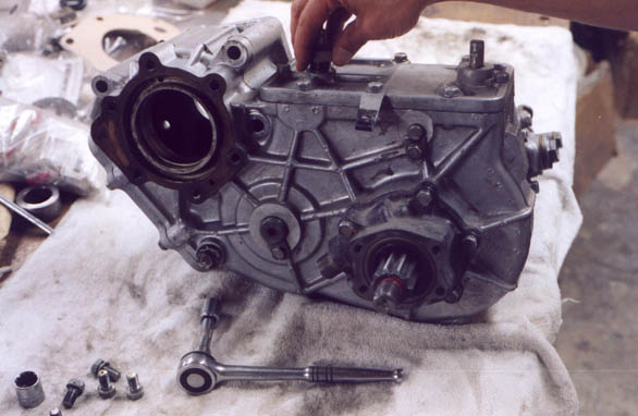
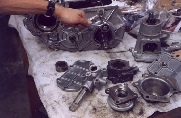
Next off is the front drive engagement mechanism, also called the "nose cone" or simply the "nose" if the transfer case. You can see the front drive engagement fork sticking out of it, and the hi range low range shifter still on it's shaft in the transfer case itself.
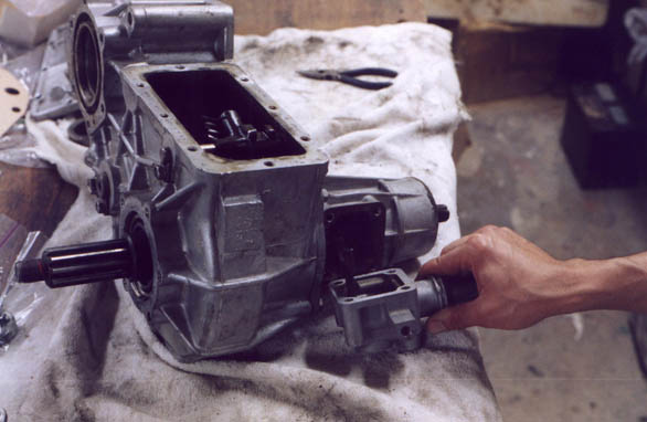
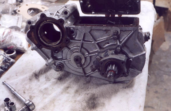
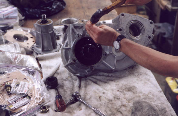
Here is the nose being pulled off the front. Yes I am a wussy and wear gloves, I learned this from a lot of pro mechanics I have observed. I use these black rubber ones for durability and solvent resistance, blue nitryl ones when I don't care too much about the durability part but need better dexterity. Each have their place and they really save your hands!
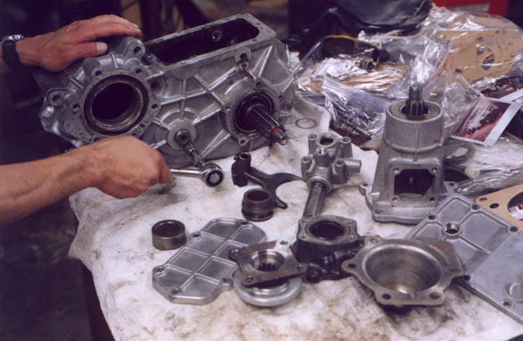
Next I remove the retainer from the high range/low range shifter. You can see all the rest of the major components of the transfer are littered about.
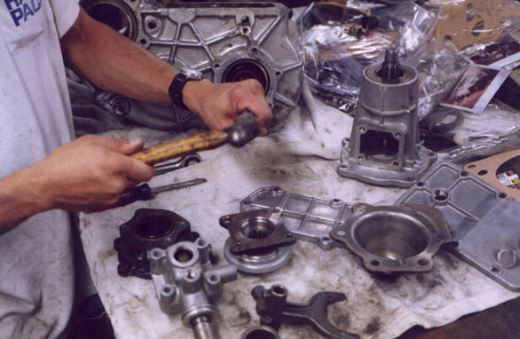
Driving the hi/low shift fork shaft with a drift.
Next we remove the retaining bolt for the idler gear cluster shaft.
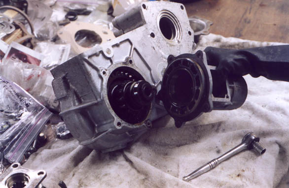
Driving the output shaft from the inner bearing race proved to be a bit of a challenge. I fabbed up an SST with my welder and some angle iron I had lying around, but ultimately I ended up boogering the threaded end of the rear ouput shaft of the t-case trying to get it unmated from the inner rear bearing races, After multi-tonne presses and many whacks, I ground the inner bearing free from the shaft, but it was already buggered. I ended up grinding the inner race off with a dremel and a stone.
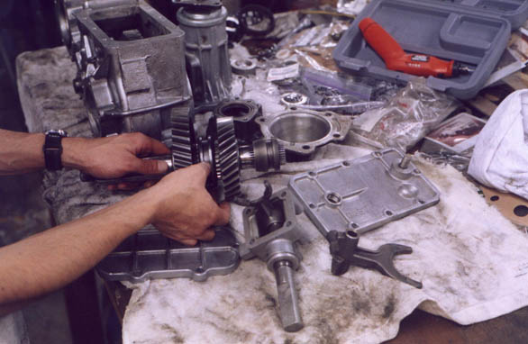
The output gear cluster is out, and visual observation leads to the conclusion that a new high speed output gear and a new shift collar ("shift clutch" in Toyota factory manual vernaculer) is required. New parts are ordered in and the resto continues....
Page 1 2
3 4 5
6 7 8
9 10 11
12 13 14
15 16 17 18
19 20 21
22 23 24
25 26 27
28 29 30
31 32 33
home what's new cruiser links trail reports cruiser sightings land cruiser tribute tech tips photos maps band links misc links profile email