Page 1 2
3 4 5
6 7 8
9 10 11
12 13 14
15 16 17
18 19 20
21 22 23
24 25 26 27
28 29 30
31 32 33
The Land
Cruiser Restoration Project
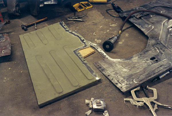
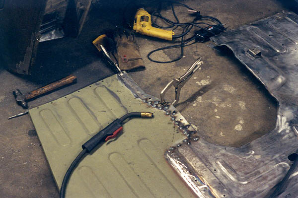
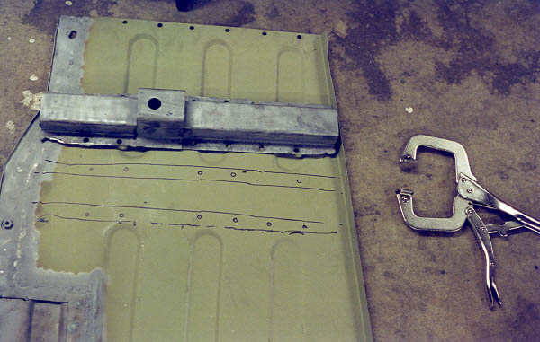
Now that the parts for the floor pan were cut to fit, I drilled out holes which were supposed to emulate the factory resistance spot welds on a lap joint when MIG welded. This was a suggestion from my local body shop guys.
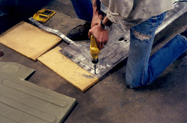
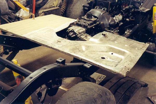
Knowing that this would be a very important fit for the whole rest of the body, I got out the old floor pan and carefully measured. One problem was because of the rot, I had to estimate some of the dimensions. With the Stanley tape measure, I tried to get measurements to within 1/16" whenever possible, but in reality I think 1/8" is all that you can hope for. Next, the new CCOT floor pan is set next to the rest and checked for fit. I used a big sharpie pen to mark where the holes were and where everything lined up.

In order to get decent welds, I would have to remove the paint from the CCOT floor pan patch panel. Out came the good old 3M abrasive wheel on the air tool!

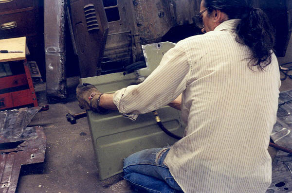
Next I lined evrything up again and clamped it down with the c-clamp vice grips and took a deep breath. This was it. If I screwed this alignment up the whole rest of the body might be a real PITA. This is my first try at this, go easy!
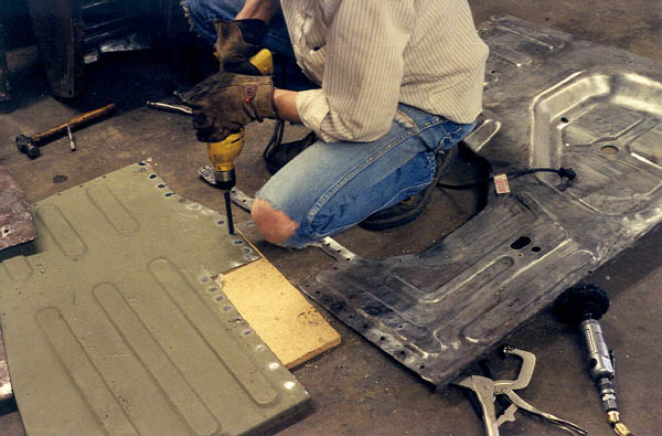
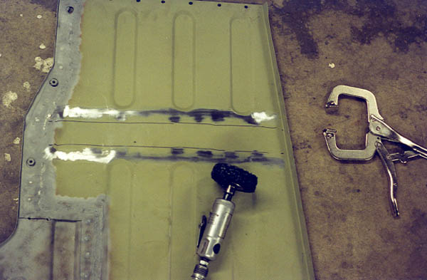
Well, I got out the helmet and fired up the TIG. I started out doing what the body guys recommended, just welding in the holes I had drilled like the original factory spot welds, even though this wasn't a location that was originally welded. I had the gas dialed in, and the heat dialed in, feed rate, it was going good. So then I got carried away and decided to push a bead along the seam. I should have listened to the body guys. They said to just do the holes, and then use a little body filler on the seams. You'll see why in a couple photos down.
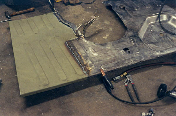
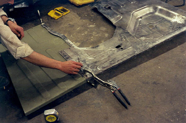
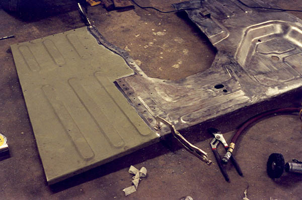
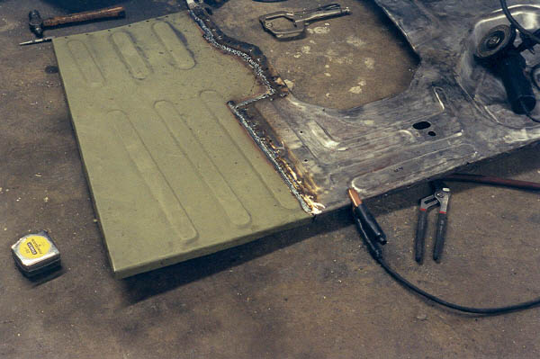
It's going good here, I have gotten away with the bead on the seam, and spot welded the next section. But you can see how the vice grips are tilted up from the start of heat warpage. But then I continue to get carried away. I did the seam bead all the way to the end of the tranny hump. It took a lot of grinding to clean up that mess, but once done, it was quite respectable. The warpage had minimal effect as it turned out to be pretty easy to straighten it out with a rubber mallet and some pices of wood. The underside shows excellent penetration with the Millermatic. Learning all the time!

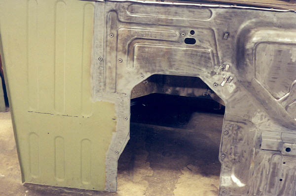
Next up was the body mount support member that goes under the driver's side floor pan. I did not want to cut this piece off until I had all my measurements and alignments for the new part welded in, so I could use the old part to reference. I cut it off with a combination of the cutoff wheel and electric angle grinder. You can see how rotted the old floor pan is, but was still clinging to a thread. Not shown, I sand blasted it inside and out.
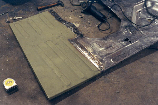
After all the grinding and sand blasting, it's about ready to weld the body mount support on. I marked where I thought it should go with a sharpie pen. Then set it on the body mounts and saw where it was really supposed to go.

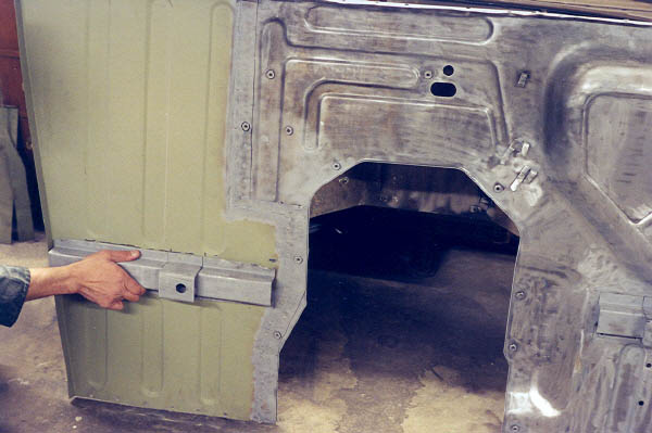
After getting it lined up with the body mounts on the frame, I used the c-clamp vice grips to hold it in position while I took the assembly back off and flipped it over. Then I marked it carefully with the sharpie pen again, and ground the paint off where I was going to be welding.

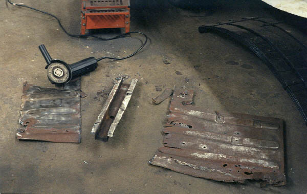
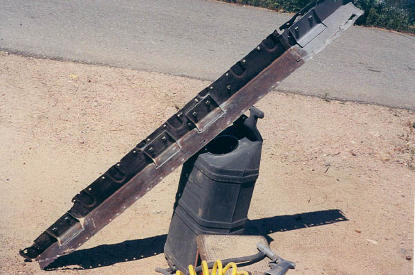
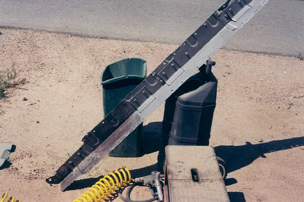
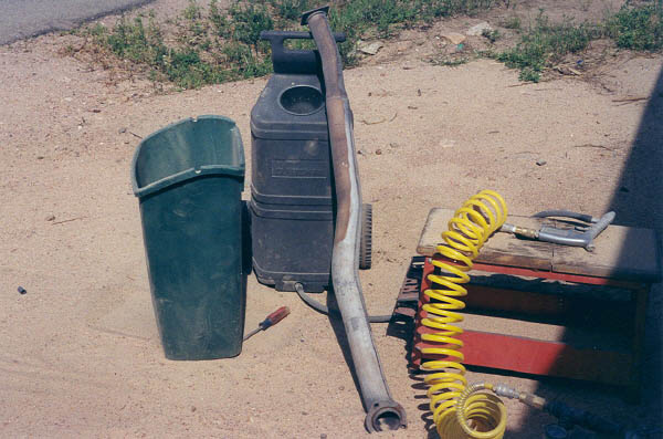
Below, I took advantage of some nice weather to get some more sand blasting done. This is the infamous "box section", which goes directly behind the seats in a 40. Actually this is one of three parts that are welded together. Some people had asked me how I was going to get the rust off the inside of these parts. Well, here's the answer: Disassemble it and sand blast down to white metal. While I was at it, I went ahead and blasted the down pipe. I would have liked to replaced it with new, but it has been discontinued and is made of unobtanium. Other than a few dents, it's actually not in too bad shape. The factory stock unit is far more desirable than any aftermarket muffler shop offering, as it is double wall and radiates much less heat and noise as a result.

Page 1 2
3 4 5
6 7 8
9 10 11
12 13 14
15 16 17
18 19 20
21 22 23
24 25 26 27
28 29 30
31 32 33
home what's new cruiser links trail reports cruiser sightings land cruiser tribute tech tips photos maps band links misc links profile email