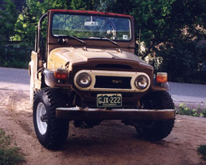
The Land Cruiser Restoration Project
Resto Home Page
Page 1 2
3 4 5
6 7 8
9 10 11
12 13 14
15 16 17
18 19 20 21
22 23 24
25 26 27
28 29 30
31 32 33
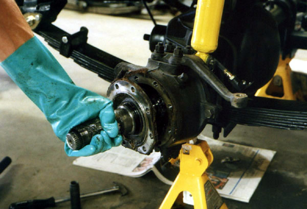
As I mentioned in my last page, these are basically 4 pages all related to the same set of jobs. Rebuild the front knuckles and brakes, swap the front dif into the rear and add a Lock Right, swap the rear diff into the front, and install new seals and gaskets onto everything. The next step after removing the steering arm is to pull the spindle. I had to give it a couple whacks with the lead shot rubber mallet to get it loose before I could just pluck it off as shown below.
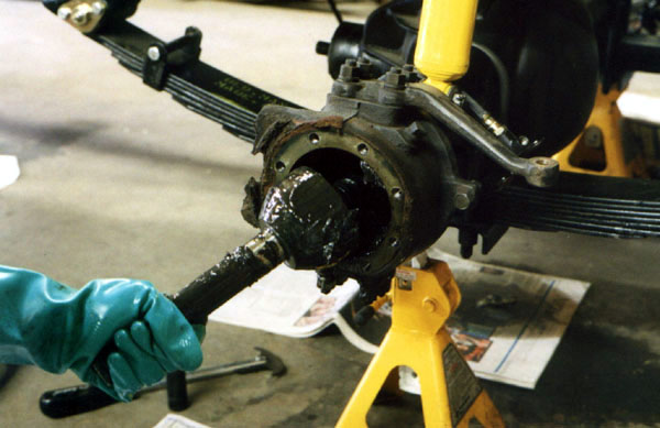
Paydirt! Here comes the birfield, all slimy and coverd with grease as it should be. Gloves for wimps? I don't think so!
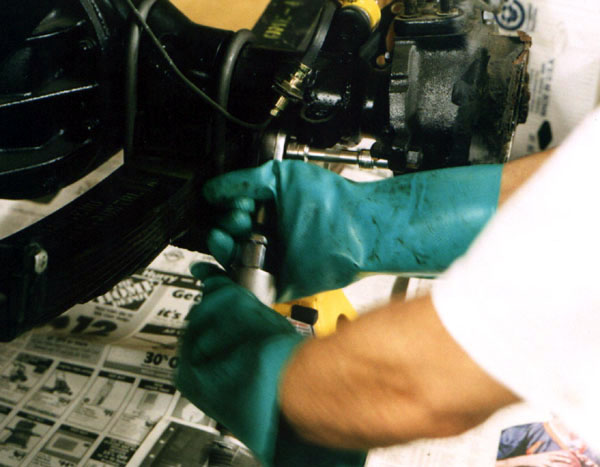
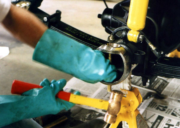
In the next two photos, I remove the 17mm nuts from the m12 studs on the bottom and then the top with my trusty air impact wrench. Air tools make jobs like this go so much faster!
Next, the retaining plates for the felts are unbolted. There are two of these, top and bottom with 4 10mm head bolts holding each one in.
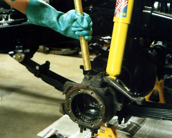
For my next trick, "watch me pull a rabbit outta my hat". "Oooops, wrong hat". :-) Anyway, there is Bruce Miller's idea of a good sized brass drift. Give a good whack on each stud, and the cone washers come loose in submission.
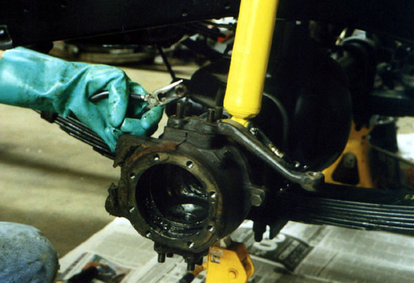
The cone washers are easily plucked out with a pair of regular long nose pliers.
I used a cold chisel and hammer to pry the steering arms off. There is a factory SST that presses them off from the inside, but it is rather costly and this method was effective and damaged nothing.
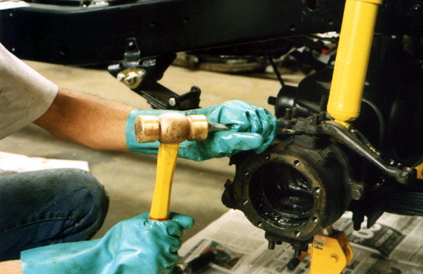
The steering arm comes right off.
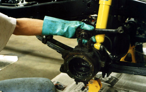
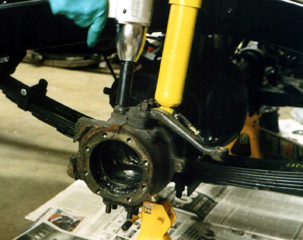
The knuckle is black and slimy with grease, as it should be.

The lower bearing retainer is driven out with a cold chisel pointed backwards so the round part is facing the retainer. When I was performing this operation on the other side, a piece of the cold chisel was flung into my arm, and I ended up with a piece of shrapnel in my arm. After a week went by and there was no sign of infection, I went to the doctor and he removed a 3.5mm x 1mm piece of hardened steel from my arm. This is an excellent reason to wear gloves and eye protection, as I always do when there is a chance of this sort of thing.

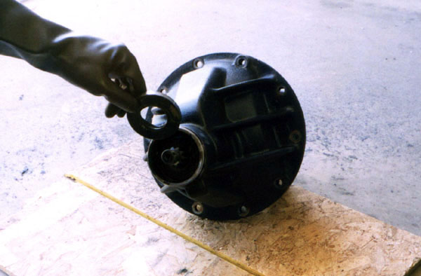
Here is the lower bearing retainer.
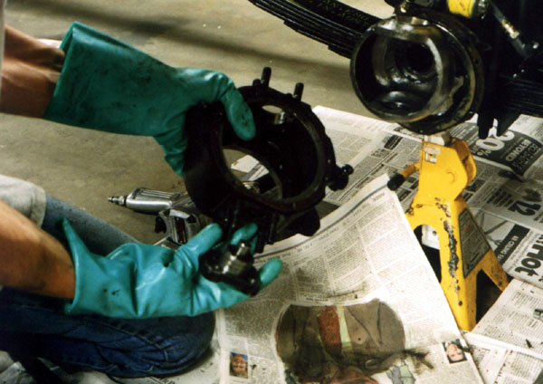
The next photo is done at an awkward angle, but I am pulling off the split ring spacer that goes closest to the inside of the knuckle. Closer to the center of the axle are the rubber ring, felt and retainer halfs that bolt to the back of the knuckle.
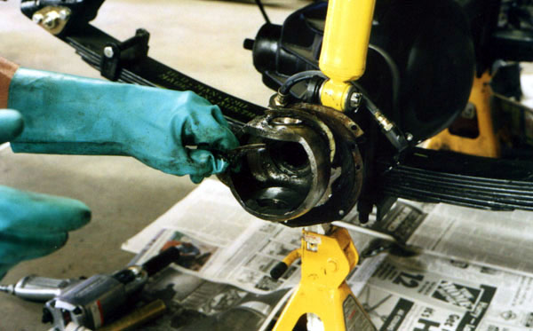
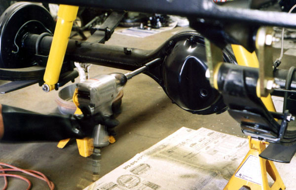
Next I drive the upper knuckle bearing race out of the axle housing end with a brass drift. Of course there is an SST for this, but the brass drift works just fine. Tap a little on the front, and then the back, keeping going back and forth and out it comes.

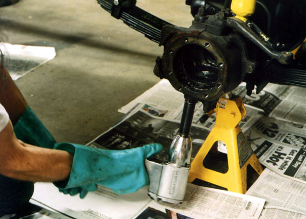
The inner axle seal is pulled out with the seal puller.

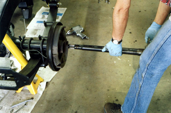
The inner axles are out so the front diff can be removed.
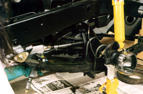
Pulling the pinion seal from the front diff.

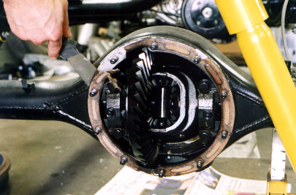
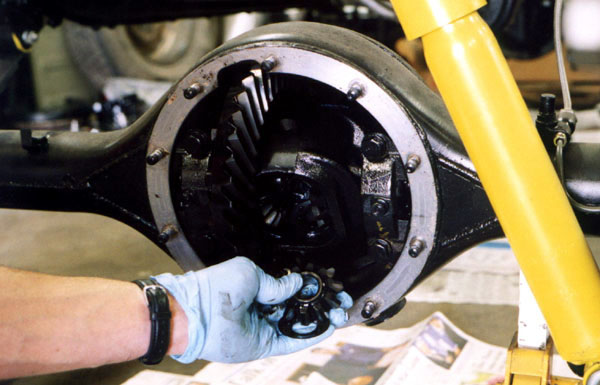
To prepare to pull the rear differential, the inspection cover nuts are removed. This turns out to be an easy job.
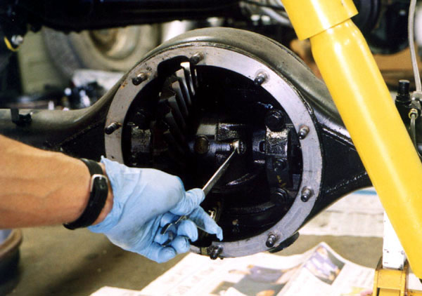
The cork gasket from the inspection cover is scraped off easily with a putty knife. I wish all of them were this easy!
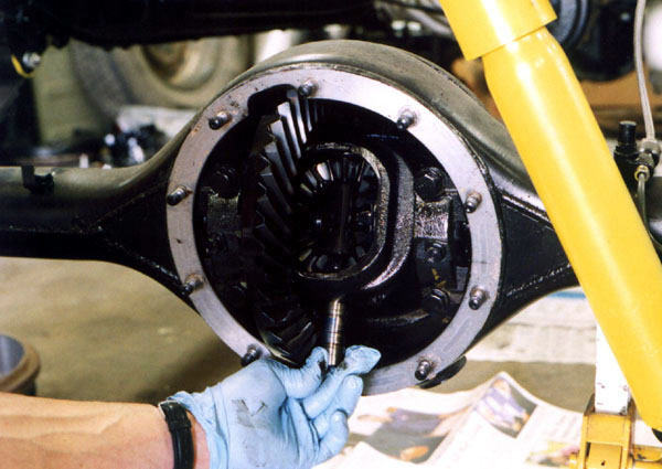
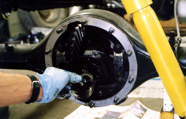
The pinion shaft itself is slid out next. Line the carrier up so that it will clear.
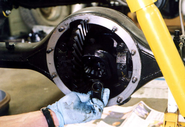
This is the spacer that goes between the inside ends of the axle shafts. It helps keep the c-clips in their grooves on a semi-floating axle.
The spider gears and their thrust washers are removed next.
The c-clips are key to SF axle.
Page 1 2
3 4 5
6 7 8
9 10 11
12 13 14
15 16 17
18 19 20 21
22 23 24
25 26 27
28 29 30
31 32 33
home what's new cruiser links trail reports cruiser sightings land cruiser tribute tech tips photos maps band links misc links profile email